How to capture a high-quality image from orbit: lessons from InnoSat16 and Lobachevsky satellites
Satellite imagery is the foundation of Earth remote sensing: it is used to assess the condition of areas and obtain data on regions that are difficult to survey regularly by other means.
How does a satellite precisely point at a selected area and capture blur-free images? How are large volumes of data transmitted from orbit to Earth, and how are monochrome images turned into color images? This article uses InnoSat16 and Lobachevsky — the first spacecraft based on the “Geoscan 16U” platform — as examples to explain how this works.
Missions of InnoSat16 and Lobachevsky
Configuring the attitude determination and control system
Improving image quality with a Kalman filter
Sharp imaging despite ground motion in TDI mode
Pointing modes during imaging
Imaging the Moon and objects in orbit
High-speed data transmission to Earth
Processing multispectral imagery
Future work
Missions of InnoSat16 and Lobachevsky
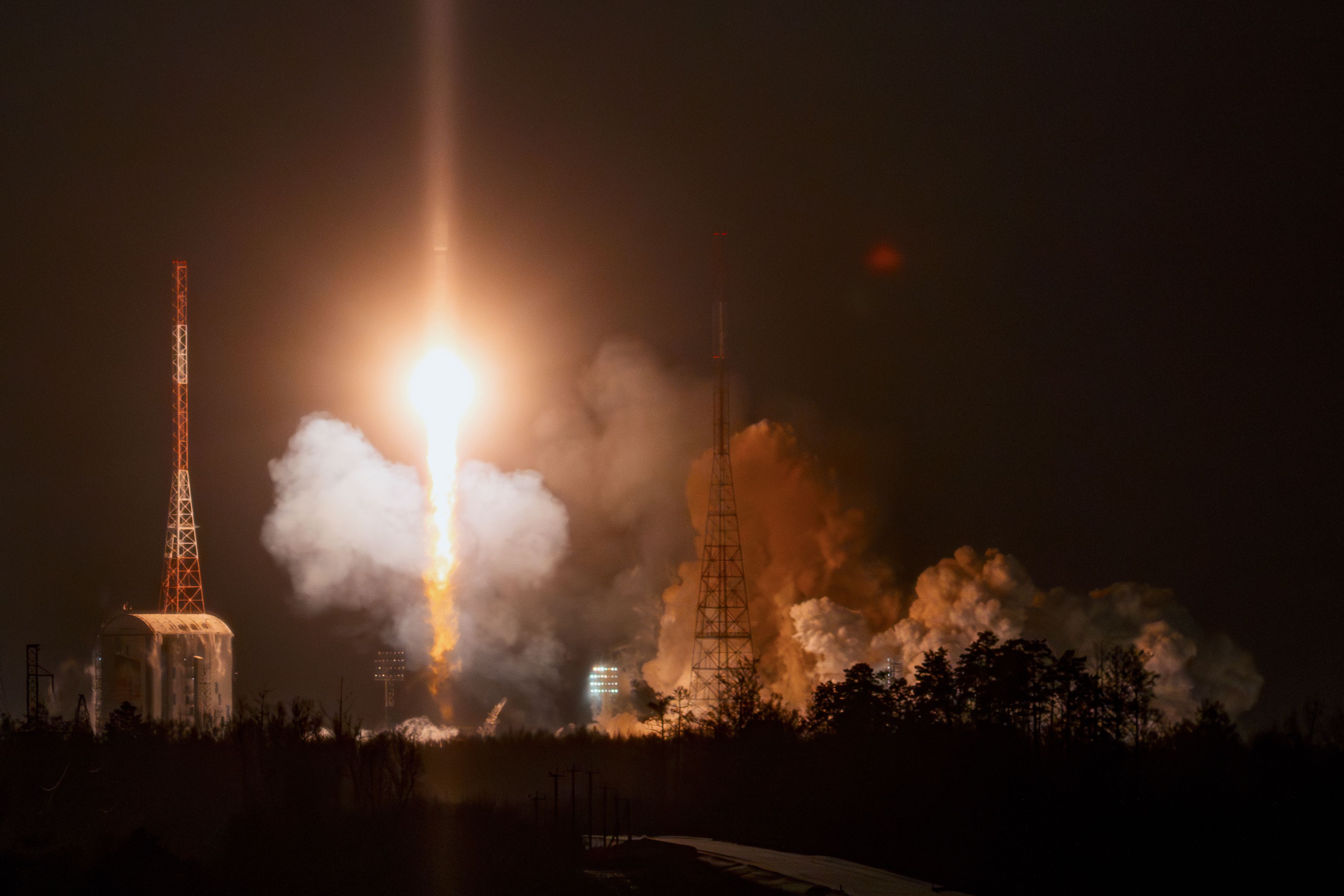
InnoSat16 was launched in summer 2025 from the Vostochny Cosmodrome. It was developed by Geoscan in collaboration with the Engineering and Innovation Support Center. In orbit, the spacecraft is verifying Earth remote sensing technologies on the 16U platform.
The satellite carries a panchromatic camera manufactured by NPO Lepton JSC, with a spatial resolution of 2.5 m/pixel from a 500 km orbit (one pixel in the image corresponds to an area of about 2.5 × 2.5 m on the ground). The camera detects light across a broad range of wavelengths and produces a single image. Such an image appears black and white and offers a high level of detail: roads, buildings, coastlines, and other ground features are clearly visible.
Lobachevsky satellite was launched in December 2025 from the Vostochny Cosmodrome. Geoscan developed it for Nizhny Novgorod State University under the Space-π project of the Foundation for Assistance to Small Innovative Enterprises. Its mission is to image Earth’s surface for agroecological research.
Lobachevsky carries a multispectral camera manufactured by NPO Lepton JSC, which is already operational, and a hyperspectral camera developed by Samara University, which is currently being configured.
The multispectral camera has a spatial resolution of 4 m/pixel from a 500 km orbit. It simultaneously captures data in four spectral bands: blue, green, red, and near infrared. These data make it possible to distinguish and analyze the properties of objects — for example, the condition of vegetation, soil, or water.
InnoSat16 and Lobachevsky satellites before integration into their launch containers
Configuring the attitude determination and control system
Imaging Earth from a satellite is like photographing a landscape from the window of a high-speed train. The satellite travels in orbit at about 7.6 km/s, Earth rotates beneath it, and the target area stays in view for only a brief moment.
Satellite image quality depends on more than the optics and the detector. The spacecraft must know where it is, where the camera is pointing, and how fast it is rotating. If attitude determination is insufficiently accurate or the satellite’s attitude control is unsteady, the ground image shifts across the detector during exposure, resulting in blur.
To point the satellite accurately at a selected area on Earth, the Geoscan team configured the attitude determination and control system (ADCS). On the Geoscan 16U platform, the ADCS relies on three groups of components: sensors measure the satellite’s attitude and motion, actuators rotate the spacecraft, and algorithms fuse the data into a picture and calculate control parameters. One of the key ADCS algorithms is the Kalman filter, which uses readings from different sensors to estimate the spacecraft’s attitude and motion parameters. The attitude algorithms were developed jointly with the Keldysh Institute of Applied Mathematics and implemented in the onboard software by Geoscan specialists.
Main components of the attitude determination and control system on the Geoscan 16U platform and their roles in spacecraft control
What the ADCS uses
Function
Sensors
Star tracker
Determines attitude from the star field
Fiber-optic gyroscope
Measures angular rates
Sun sensors
Help determine the satellite’s attitude in less precise modes
Magnetometers
Navigation receiver
Determines the satellite’s position in orbit
Actuators
Reaction wheels
Rotate and stabilize the satellite
Magnetorquer coils
Help control attitude using Earth’s magnetic field
Algorithms
B-Dot algorithm
Damps unwanted spacecraft rotation, for example after deployment from the container
Kalman filters
Estimate spacecraft attitude and motion parameters from readings of different sensors
Configuration of the attitude determination and control system proceeded in stages: from basic checks of the sensors and actuators to imaging with the payload. During testing, the team:
verified the alignment of the sensors, reaction wheels, magnetorquer coils, and cameras with the spacecraft body-centered coordinate system;
verified operation of the navigation receiver and orbital filter;
tested the B-Dot algorithm;
tuned the Kalman filter for communications, which uses sun sensors, magnetometers, and the fiber-optic gyroscope;
tuned the Kalman filter for imaging, which uses the star tracker and the fiber-optic gyroscope;
verified operation of the Cyclops engineering cameras developed by Geoscan and the payload cameras developed by NPO Lepton JSC on both satellites.
The key stage was tuning the imaging Kalman filter — this brought the attitude system to the accuracy required for Earth observation.
Improving image quality with a Kalman filter
The imaging Kalman filter compares data from the star tracker and fiber-optic gyroscope, accounts for measurement errors, and reduces the impact of noise. Based on these data, the algorithm produces a more accurate and smoother attitude estimate.
After the filter was tuned, the attitude determination error fell below 0.01°, while the attitude-holding error was below 0.005°/s. The first metric indicates how accurately the camera points at the selected area on Earth. At an altitude of about 500 km, an angle of 0.01° corresponds to roughly 90 m on the ground — in other words, the satellite can point at the required area with an accuracy comparable to the size of a city block. The second metric reflects pointing stability: the lower the angular rate during the exposure, the less the image drifts across the detector and the lower the risk of blur.
The filter’s performance was verified using in-flight logs. During attitude-system tests, the satellite recorded subsystem telemetry, including attitude angles and angular rates. The resulting data were transmitted to Earth over the X-band link for subsequent analysis.
Satellite logs. Left — spacecraft attitude angles about three axes; right — angular rates. Horizontal axis — time, s. Between 1600 and 1700 seconds, star-tracker correction is temporarily disabled: the filter propagates the attitude estimate using the fiber-optic gyroscope to enhance pointing stability during imaging
The chart on the left shows the spacecraft’s attitude angles: yaw, pitch, and roll. The blue dots are individual star-tracker measurements; the orange line is the Kalman filter estimate. The star-tracker measurements are visibly scattered, while the filter uses them to produce a smoother attitude estimate. The chart on the right shows angular rates about the same three axes. The target value during imaging was an angular rate below 0.005°/s: at this level, the image shifts less across the detector during the exposure.
Between 1600 and 1700 seconds, correction from the star tracker was temporarily disabled, and the filter propagated the attitude estimate using data from the fiber-optic gyroscope. This helps improve pointing stability over a short imaging interval: the gyroscope continuously tracks the spacecraft’s rotation, while the system avoids unnecessary corrections caused by noisy star-tracker measurements. After correction was re-enabled at about 1720 seconds, a brief transient appears on the chart as the filter re-converges the attitude estimate using star-tracker data.
The effect of the tuning became visible in the images. Early images from InnoSat16 were blurred: during a 3 ms exposure, the ground image shifted across the detector by about 5 pixels. After the Kalman filter was tuned, the images became sharper.
Examples of images from InnoSat16 before and after tuning the Kalman filter. Left — an area in the USA imaged before tuning; right — an area in the USA after tuning
Sharp imaging despite ground motion in TDI mode
Even with precise attitude control, imaging from orbit remains a complex task: the satellite moves around Earth, Earth itself rotates, and the image of the surface moves across the camera detector during imaging.
With an average exposure time of 5 ms and a satellite velocity relative to the target point of about 7.1 km/s, the imaged area shifts by roughly 35 m during the exposure. For a camera where one pixel corresponds to about 4.1 m on the ground, this is roughly 8 pixels — without compensation, the image would be blurred.
Time delay integration (TDI) mode prevents this blur. During the exposure, the accumulated signal is shifted along the detector rows in step with the motion of the image. TDI mode imposes stricter requirements on the satellite’s motion and attitude: the shift rate must match the velocity of the ground image across the detector, and the direction must be exactly aligned with the TDI axis.
Examples of images from InnoSat16 before and after TDI mode was enabled. Left — an area in the USA imaged without TDI; right — an area in the UAE after switching to TDI. Even cars can be distinguished in the image on the right
Pointing modes during imaging
Once the attitude system is configured, the spacecraft can switch between different imaging modes. Depending on the task, it can point at nadir, repositioning between targets, or track another object in orbit.
On InnoSat16 and Lobachevsky, several such modes were tested. During nadir imaging, the camera was pointed at the area directly beneath the satellite, and imaging proceeded along the ground track. In point-tracking mode, the spacecraft continuously slewed so that the selected target remained in the center of the frame throughout the pass. Lobachevsky also performed retargeting between objects: about one minute after the slew, the satellite returned to its required stabilization accuracy and resumed imaging.
A separate scenario involved pointing at an object to be observed (for example, another spacecraft) using TLE data (a two-line element set). This is a set of orbital parameters that can be used to calculate an object’s position in orbit. We later used this mode in an experiment to image a launch vehicle stage.
Imaging the Moon and objects in orbit
In addition to imaging Earth, the Geoscan team tested more complex pointing scenarios for other targets: the Moon, another spacecraft, and a piece of space debris.
Images of the Moon were taken during attitude-system testing on InnoSat16. The specialists verified pointing accuracy, the ability to keep the target in the frame, and operation of the panchromatic camera. The resulting images show lunar surface features and individual craters.
Image of the Moon from InnoSat16
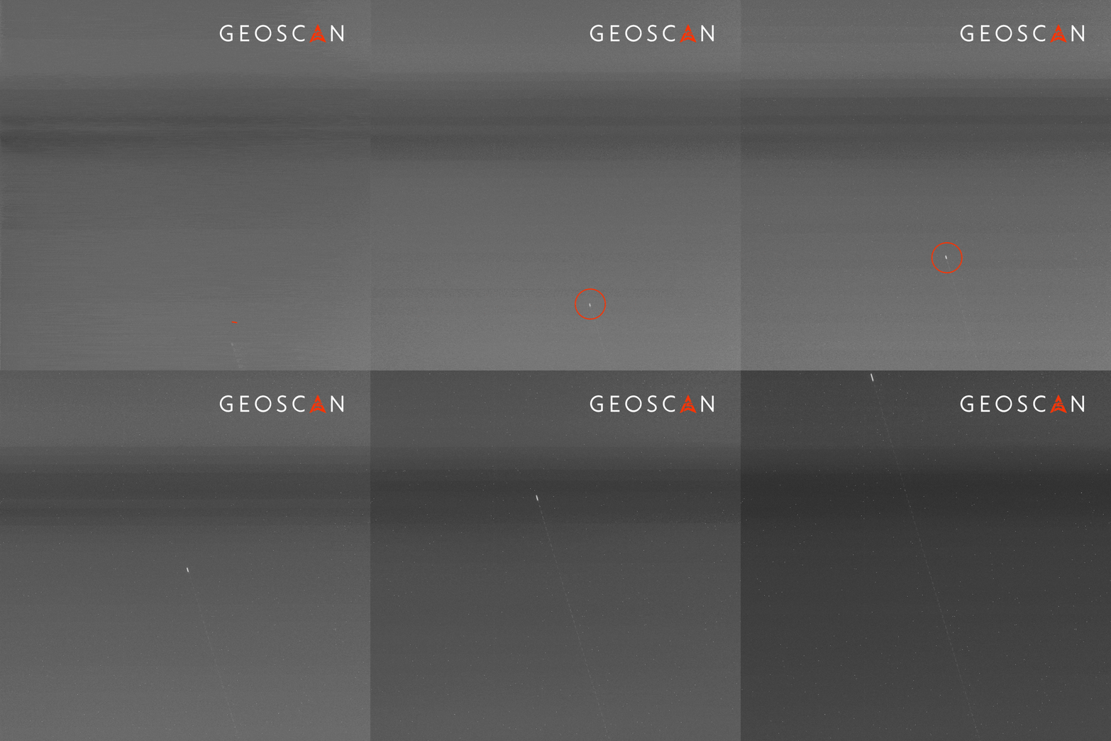
In June, together with the Faculty of Space Research at Moscow State University, the team conducted experiments to image objects in orbit. They tested whether the satellite could predict a close approach with another object, point at it, and capture images during the flyby.
For these observations, specialists from the Faculty of Space Research at Moscow State University calculated close-approach time windows with suitable illumination conditions and prepared targeting commands that were updated using current orbital data. During the experiments, Lobachevsky performed a pointing test on a Japanese launch vehicle stage that remained in orbit after the launch of the GOSAT-2 satellite in 2018, while InnoSat16 captured images of the Russian scientific spacecraft Koronas-Foton, which was decommissioned in 2010. In both cases, imaging was performed from a distance of about 60 km.
Motion of the launch vehicle stage in images from Lobachevsky satellite
Motion of the Koronas-Foton spacecraft in images from InnoSat16 satellite
High-speed data transmission to Earth
After an imaging session, large volumes of data remain stored onboard the 16U satellites, including raw images, attitude logs, and records of other parameters. To transmit such volumes of information, the Geoscan team tested the high-speed X-band radio link on InnoSat16 and Lobachevsky. It consists of a Geoscan-developed onboard transmitter and a ground receiving station with a steerable parabolic antenna. When the satellite passes over the station, the antenna tracks it while the satellite transmits the stored data.
The transmitter operates in the amateur-radio X-band at 10.5 GHz and uses the widely adopted DVB-S2 standard. Its data rate is 250 Mbit/s. Because the transmitter power is only 1 W, it is important to concentrate the signal in the direction of the ground station. To do this, an 8 × 8 antenna array with a gain of 20 dBi forms a directional radio beam and helps transmit a large volume of data during a short communication session.
During testing, the Geoscan team confirmed data reception at 155 Mbit/s. The 16U platforms also use a bidirectional UHF command-and-telemetry link at up to 9,600 bit/s — for spacecraft control, telemetry reception, and low-rate data transmission. The X-band data rate is more than 16,000 times higher, so it can carry not only service information but also large images and datasets.
Processing multispectral imagery
Among the data transmitted to Earth over the X-band link are the raw multispectral camera data — monochrome strips. How are they turned into color images?
The Lobachevsky multispectral camera uses a single detector, with four narrow optical-filter strips bonded over it that pass red, green, blue, and infrared light. As the satellite moves, the image of the same area on Earth’s surface passes sequentially over detector regions beneath different filters, so the data for a color image are collected from a series of frames.
The raw frames are first split along the boundaries of the four optical filters. The fragments from each spectral band are then aligned using ground landmarks or geographic coordinates. This produces separate monochrome images in the red, green, blue, and near-infrared bands. To create color images from Lobachevsky, the first three channels were combined.
Left — a raw monochrome image from the Lobachevsky multispectral camera, showing an area in Egypt. Right — a color image assembled from the red, green, and blue channels, showing an area in the USA
Future work
The first images from InnoSat16 and Lobachevsky confirmed the performance of the platform, attitude system, cameras, and X-band radio link.
One of the main tasks now is focusing the Earth-observation cameras. In space, focusing is affected by the spacecraft’s thermal environment: the optical and digital units heat up and cool down differently, so the focus must be adjusted on orbit by correlating camera parameters, temperature, and the resulting images. At the same time, the team continues to optimize imaging parameters: exposure time, the number of TDI stages, attitude modes, and the conditions under which the camera produces the most informative results.
Future plans include developing a unified software suite that integrates spacecraft control, imaging planning, and data reception, processing, storage, and distribution. The Geoscan team also plans to expand its network of data receiving stations.
Monitoring near-Earth space, tracking the dynamics of Earth’s radiation belts, and forecasting space weather are tasks that instruments in orbit, built in various countries, are addressing today. A team from the Laboratory of Geospace Research at NRNU MEPhI – staff, students, and schoolchildren – is developing its own version of such an instrument
Amateur Radio Broadcasting Event:
from September 11 to 20, 2026, amateur radio digital broadcasts of postcards will be conducted almost worldwide from the Geoscan-2, Geoscan-4, and Geoscan-5 satellites using Geoscan’s own protocol
The Svetlana spectrometer will enable simultaneous detection of energetic electron fluxes from the radiation belt and atmospheric glow within the auroral oval directly aboard a CubeSat
In Moscow, the Geoscan company gathered schoolchildren, students, specialists and space enthusiasts to discuss the present and future of space exploration
New items in the encyclopedia and the latest news.
We will write to you only when something interesting appears, no space junk